
Thermoelectromagnetics
Introduction
Thermoelectromagnetics refers to physical processes involving both the thermal field and the electromagnetic fields. This section introduces three major mechanisms in thermoelectromagnetics: Joule heating, dielectric heating, and induction heating.
$\space$Joule Heating
Joule heating (also referred to as resistive or Ohmic heating) describes the process where the energy of an electric current is converted into heat as it flows through a resistive conductor. Joule heating is caused by the interactions between the moving particles constituting the current, which are, usually but not always, electrons, and the atomic ions constituting the body of the conductor.
The differential form of the Joule heating equation calculates the power per unit volume: \[{dP_{\rm e}}^{\rm f}/dV ={J_{\rm e}}^{\rm f} \cdot E,\] where $J_{{\rm e}}^{{\rm f}} $ is the current density and $E$ is the electric field. For a neutral plasma in a magnetic field and with a conductivity of $\sigma $, we have $J_{{\rm e}}^{{\rm f}} =\sigma E$, hence, \[{dP_{\rm e}}^{\rm f} / dV ={J_{\rm e}}^{\rm f} \cdot E ={J_{\rm e}}^{\rm f} \cdot {J_{\rm e}}^{\rm f}/\sigma=\rho \left|J_{{\rm e}}^{{\rm f}} \right|^{2}=\sigma \left|E\right|^{2}\] where $\rho ={1 /\sigma } $ is the resistivity. This equation resembles the "$I^{2} R$" term in the macroscopic form of the Joule heating equation.
$\space$Dielectric Heating
Dielectric heating is also known as electronic heating, RF heating, and high-frequency heating. It is the conversion of electromagnetic energy into thermal energy in dielectric materials caused by a high-frequency alternating electric field, radio wave, or microwave electromagnetic radiation. There are two slightly different heating types, i.e., RF heating and microwave heating. Both types of dielectric heating are induced by dipole rotation. In the RF heating, the applied electromagnetic radiation usually has a frequency between 3 and 300 MHz. Therefore, the heated objects are generally smaller than the wavelength. Microwave heating, distinct from RF heating, are associated with frequencies above 100 MHz. Due to the reason, an electromagnetic wave can be launched from a small dimension emitter and guided through space to the target to be heated.
In dielectric heating, the density of generated heat per a unit volume is \[P_{{\rm e}}^{{\rm d}} =\omega \varepsilon _{{\rm r}}^{'} \varepsilon _{0} \left|E\right|^{2} , \] where $\omega $ is the angular frequency of the external field, $\varepsilon _{{\rm r}}^{'} $ is the imaginary part of the complex relative permittivity of the heated material, $\varepsilon _{0} $ is the permittivity of vacuum, and $\left|E\right|$ is the electric field strength. The imaginary part of the relative permittivity, which is also frequency-dependent, is a measure of the ability of a dielectric material to convert electromagnetic energy into heat. As we know, $\sigma $ determines Joule heating. But in the case of a low $\sigma $ and a high $\omega $ value, i.e., $\sigma <<\omega \varepsilon _{{\rm r}}^{'} \varepsilon _{0} $, dielectric heating is the dominant mechanism for energy conversion from the electromagnetic field to the thermal field.
$\space$Induction Heating
Poynting's theorem is a relation between the changing rate of the energy stored in the field and the energy flow. Multiplying Faraday's law and Ampére's law and ignoring the displacement current with the electric and magnetic field leads to \[\oint _{s}\left(E\times H\right) \cdot ndA=-\int _{v}H\cdot \frac{\partial B}{\partial t} dV-\int _{v}\sigma E\cdot EdV , \] where the quantity $E\times H$ is known as the Poynting vector $P_{{\rm EM}} $ in ${W/m}^{2}$. Poynting's theorem states that the sum of the Ohmic loss and the power absorbed by the magnetic field in the volume is equal to the total power input.
It is common to represent a harmonic variation in time as a complex function of coordinates, multiplied by the factor, $e^{i\omega t} $. The complex Poynting vector can, therefore, be written as \[P_{{\rm EM}} =\frac{1}{2} \left(E\times H\right), \] and its integral is \[\oint _{s}P_{{\rm EM}} dS =-\frac{1}{2} j\omega \int _{v}\mu \left|H\right|^{2} dV -\frac{1}{2} \int _{v}\sigma \left|E\right|^{2} dV . \] The real part of the above equation determines the energy dissipated into heat (ohmic losses) in the volume V and the imaginary part is equal to $2\omega $ times of the mean value of the magnetic energy. The current from the real part is known as the eddy current and is the main heat source in induction heating.
Example
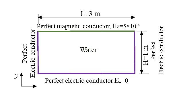
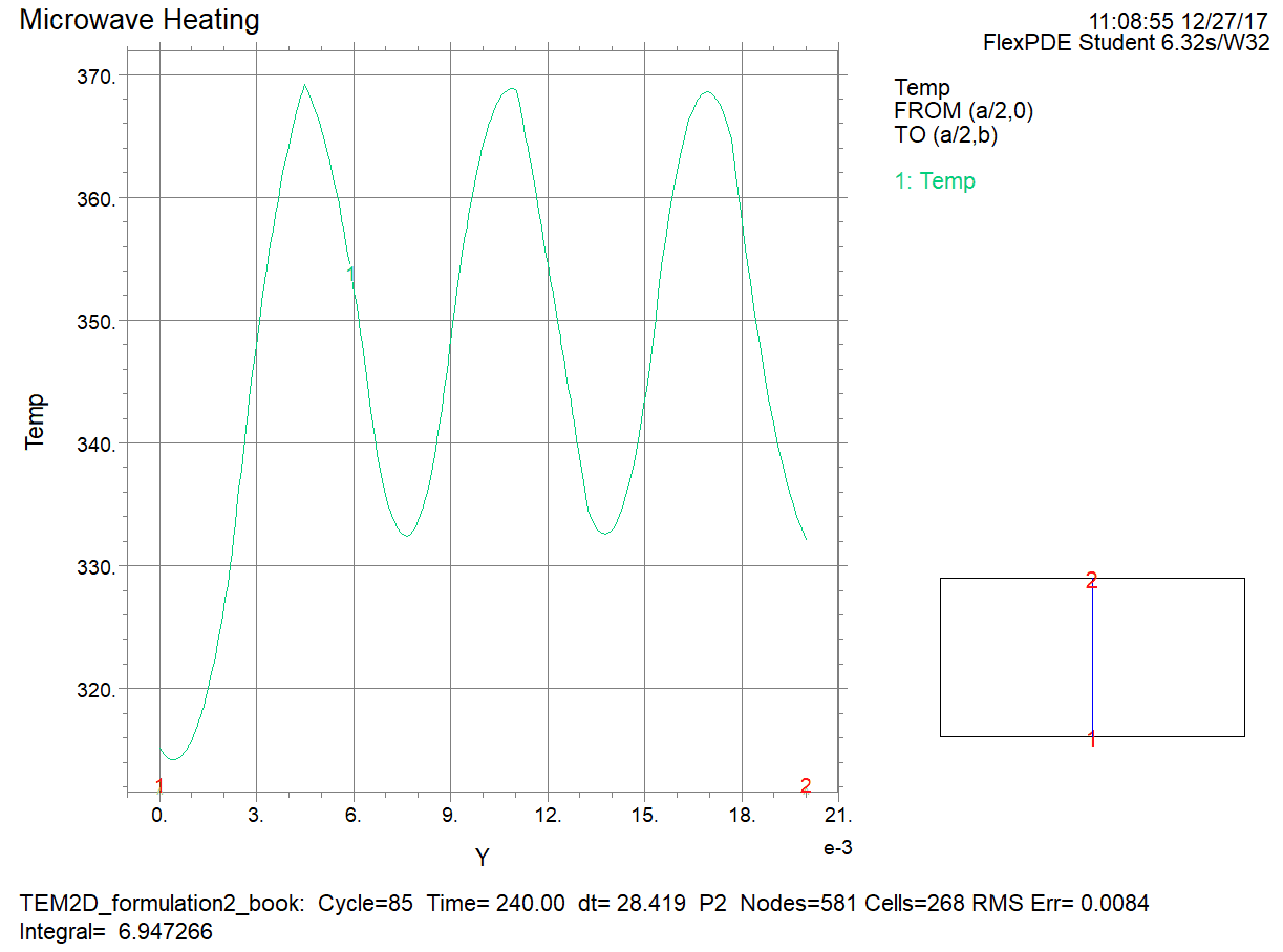
As shown in the following figure, a long box with a cross-section of 0.04 m by 0.02 m contains water. All the side surfaces and the two end surfaces (two ends of the longitudinal direction) are metals, which can be formulated as perfect electric conductors ($\nabla \times E=0$). One side surface is perfect magnetic conductors ($\nabla \times H=0$). The box contains water which has a relative permittivity of 78+12i. An electromagnetic wave with a frequency of 2.45 GHz was generated, whose wave number along the longitudinal direction is 0.4 of the total wave number. Please predict the temperature distribution on the path of x=0.02 m at the end of 4 minutes.